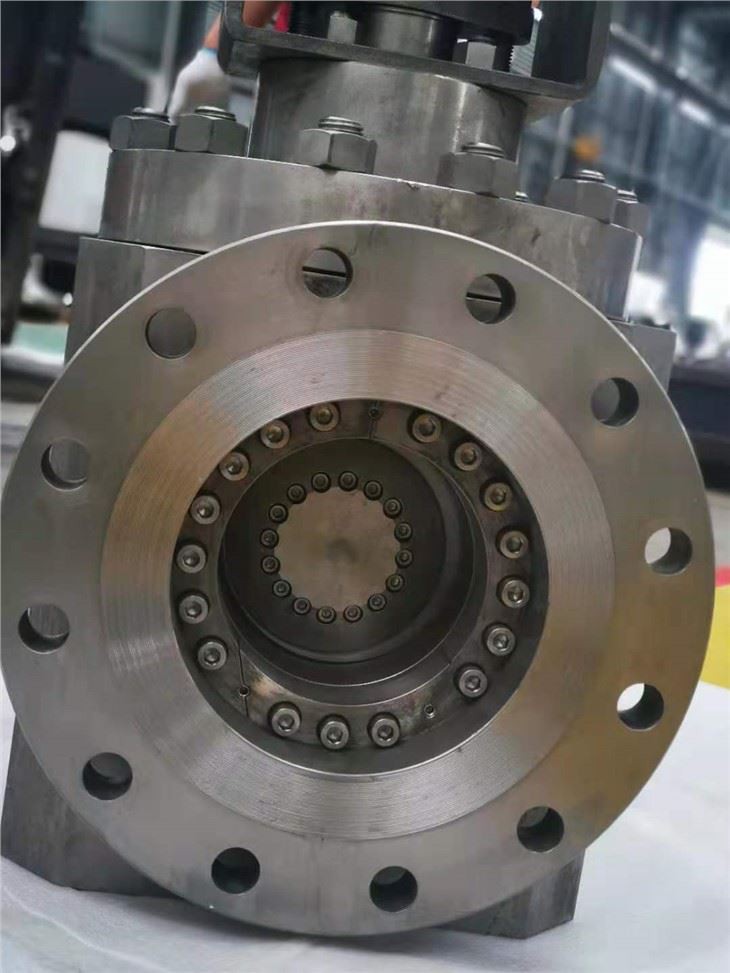


Metal To Metal Valve
MF Series
Metal to Metal Floating Seat Bi-directional Sealing
Triple Eccentric Butterfly Valve
Send Inquiry
Product Details ofMetal To Metal Valve
Installation, Operation and Maintenance Manual MF Series Metal to Metal Floating Seat Bi-directional Sealing Triple Eccentric Butterfly Valve |
|

Please read the manual carefully before installation and usage
1.General information
1.1scope
The manual applies to MF Triple Eccentric Butterfly Valve. Actuators and other parts are only introduced briefly in this manual. If more detailed information is needed, refer to the relevant actuator manual.
notice:
An overall consideration in details is needed when choosing and using valves in special working conditions. This manual does not introduce all possible circumstances in using of valves due to different product types. If you are unsure about how to use the valve or if this manual is effective, contact us for more information
1.2valve structure
MF series valve is Metal to Metal Floating Seat Bi-directional Sealing Triple Eccentric Butterfly Valve. M refers to full metal butterfly valve and F to floating seat butterfly valve.
The valve that is made of forged steel A105 can be welded directly to pipes without pre-heating.
The floating seat of the valve developed from the triple eccentric basis. When there is a back pressure of medium in the closed valve, movable floating seat will move towards the disc slightly to ensure a snug fit between the seat and the seal ring to achieve zero leakage in back pressure as in positive seating.
The butterfly disc and the shaft are connected by pin.
The valve is usually applied to heating-supply network and steam pipe network, playing a role mainly in opening, closing and regulating.

1.3Valve body mark
Valve size Valve pressure
Valve flow direction arrow
The big arrow means the main sealing direction.
The little arrow means the minor sealing direction- more commonly known as reverse sealing direction in eccentric butterfly valve.
1.4 technical specifications Connection: BW pressure rating: PN25
temperature range: -29℃~+425℃
flow direction: both upstream and downstream Proposed installing direction:
The big arrow points the main sealing direction The little arrow points the minor sealing direction
1.5 safety measures Warning:
Do not exceed the limitation of valve parameters in use!
Exceeding the limitation of valve parameters in use could cause damage to the valve and uncontrollable pressure relief which can result in safety accident.
Warning:
Do not remove or move the valve under pressure in the pipeline. Removing and moving of the valve under pressure could cause uncontrollable pressure relief. Before removing the valve, remove related components in the pipeline to release pressure and to empty medium. Make sure what medium it is in the pipeline in the first place to prevent people and environment from poisoning. Make sure that nothing enters the pipeline during maintenance, otherwise it may cause damage to the valve or safety accident.
Warning:
Notice the cutting motion of the butterfly disc!
Keep your hands, other body parts, tools and other stuff away from opening fluid passages. Make sure that there is no foreign substance in the pipeline. The butterfly disc functions like a cutting device when the valve is being driven. The butterfly disc may shift when the valve is being moved. Close or remove the actuator in the valve repair, otherwise it may cause damage to the valve or safety accident.
Warning:
Notice the noise!
The valve may make noise in the pipeline and the noise level is based on working conditions.
Warning:
Notice the overheating of valve!
The valve body will overheat in use when the medium is high temperature water or high temperature steam. Be careful to prevent people from scalding.
Warning:
Learn its weight when lifting or packing the valve.
Do not lift the valve through its actuator, positioner, limit switches or pipeline. Lift the valve through its lug (if any) or by ropes tightly bound to the valve body (as shown in Figure 3). Otherwise the falling parts may cause damage to the valve or safety accident.
Notice:
Do not rotate the butterfly disc over 90 degree, otherwise it may cause damage to the valve. The rotation angle of the butterfly disc is designed to be 0 degree to 90 degree.
Notice:
If users need do pressure testing with this type of valves, ple ase pay attention to the sealing parts(sealing ring and seat), any small particles in the air or water will case irreparable da mage. The best way to check small particles on the sealing p arts is not by eye but by hands touching.
2.Transportation, shipping and storage
Examine the valve and related components to find possible resulting damage in transportation. The valve should be kept carefully, preferably in a dry room before the installation.
Before the installation, do not put the valve in the installation position or remove the protector in the port.
the valve should be closed during delivery and be closed slightly in storage.
3.Installation
3.1general rules Warning:
Learn its weight when lifting or packing the valve. Follow the way as shown in figure 3.

Remove the protector in the port and check if the valve is damaged and clean inside.
Do not move the actuator before the installation if the manufacturer has installed it before delivery.
Installing or adjusting the actuator improperly after moving it may cause damage to the valve or the leak.
Shut the valve completely before welding it to the pipeline. Lift the valve onto the pipeline as shown in figure 3. Be careful to follow the safety measures in section 15.
If the valve is being welded to a vertical line, shut the valve and cover its surface with a water cushion of 50mm to prevent the welding spatter and damage to the seat or the sealing surface that caused by flux.
The valve can be installed with the shaft at a horizontal position or a vertical position. It is recommended to point the main sealing direction with the big arrow and the minor sealing direction with the little arrow.
The oxygenated water or the air will accelerate the corrosion of the outlet when the valve is installed in a centralized heating system. To prevent the corrosion, empty the area behind the valve and fill it with oxygen-free hot water (as shown in figure 4).)

the fluid may cause so-called dynamic torque to stop the valve from being shut. the pressure of the elbow on the outside is way higher than that on the inside.
if the triple Eccentric Butterfly Valve is installed directly behind a bent sub, its shaft should point straight to the center of the pipe (as shown in figure 5). This is very important especially when the valve is used as a control valve.
If the valve is installed behind a centrifugal pump, its shaft should be perpendicular to the pump spindle (as shown in figure 6).
the load and the vibration of the butterfly disc will be more stable if the valve is installed following the steps above. It will also eliminate the possible chatter in the middle of the valve.

3.3preparation before test run
flush the pipe carefully. keep the valve open at a degree between 30 and 40 during the flushing procedure.
shut the valve if the butterfly disc opens at a degree between 5 and 10 during the flushing procedure. accelerate the flow of the washing fluid to flush out the residual impurity.
even the tiny impurity may cause irreversible damage to the sealing surface when the valve is closed.
3.4test run
make sure the valve in the pipeline is closed or opened at an angle no large than 20 degree before turning on the pump.
4.Maintenance
warning:
learn all the safety measures listed in section 1.5 before maintenance.
the triple Eccentric Butterfly Valve does not require scheduled maintenance but scheduled inspection for the packing to ensure its sealing. basic repairs will be enough if the valve needs to be fixed for some reason.
see the components on the assembly drawing in section 8 for the valve structure.
4.1replacing the packing (graphite)
warning: do not remove the valve from the pipeline under pressure.
1.remove the actuator (as shown in section 5.2) and the keys on the shaft.
2.remove the packing gland (16).
3.flush the shaft especially the part that contacts with the packing gland.
4.install the new packing ring. 5.install the packing gland.
6.reinstall the actuator.
5.Removing and installing the actuator
5.1general rules warning:
learn its weight before lifting or packing the valve
notice: this section do not include the instruction for pneumatic or motorized actuators. refer to the instruction for installing gear. see the confirmation of order for the selection, torque and platform of pneumatic or motorized actuators.
5.2remove the actuator (gear) warning:
do not remove the actuator from the valve under pressure due to the possible dynamic torque caused by the pipeline!
notice:
note the position of the actuator before uninstallation to ensure proper reinstallation.
the actuator is usually installed by the manufacturer with all the limited nuts preset.
1.shut off the pressure of the medium in the pipeline to ensure that the valve is without pressure.
2.removing the screw between the actuator and the Connecting Yoke.
3.use proper tools and lifting-up devices to remove the actuator.
4.if any, remove the yoke and the coupling.
5.3installing the actuator (turbine) on the valve. 1.assemble the yoke and the valve( if any).
2.check and make sure that the valve is closed before installing the actuator.
3.flush any attachment that may affect installation away from the shaft and the keys.
4.if a shaft sleeve is needed between the the actuator and the shaft, it should be installed on the top of the input shaft.
5.the keyway on the shaft should be vertical to the surface of the butterfly disc when the valve is closed.
6.make sure that the actuator output shaft hole is consistent with the valve stem input end with using the wheel of the actuator.
7.hoist the actuator steadily and check if the actuator is installed properly.
8.the size of the extended stem (if needed) should be discussed with the valve manufacturer,
6Maintenance does not require special tools.
7Order of replacement parts
the following information is needed when ordering replacement parts:
the valve type, the order number and the serial number (the stamp on the valve body)
the number and the name of the part on the drawing and its required quantity.
those information can be acquired from the related valve ordering documentation.
(part of the materials is subject to the actual confirmation drawing of order while the material selection for components in this manual is merely recommended)
|

Hot Tags: metal to metal valve, China, manufacturers, factory, customized, wholesale, price, cheap, in stock, for sale, free sample, eccentric butterfly valve, triple offset butterfly valve, butterfly valves, flanged special material valve, y type special material valve, grooved end special material valve
Next
No InformationSend Inquiry